N.B. This web page is only intended to help you work on your mower, but I don't take any responsibility for any damage or injuries which result.
Working on the mower.
For the following, I have quoted the Qualcast part names and the part numbers shown on the diagrams above.
You may find it helpful to print out the parts diagrams to refer to.
Don't forget - the side quoted is as viewed when pushing the mower.
|
Before dismantling.
|
|
This shows my mower, before working on it.
The R.H. wheel assembly is the original blue'ish colour, with the addition of some trendy rust!
|
|
|
This shows the underneath of the mower, before working on it.
Now, before doing anything else, is a good time to go round all the nuts and bolts, etc. with penetrating oil.
|
|
|
Now, turn the mower so that the R.H. wheel (1) and side plate (5) are uppermost.
Note the handy arrow telling you which way to push the mower. This also shows the position for the oiling points, on the wheels, required to oil the drive pinions.
One thing to point out here is that, with the roller adjusted at this height, it is quite possible for the roller pin (19), which acts as its axle, to work loose during use and fall out.
|
|
Dismantling.
|
Step 1.
Firstly, lever off the spigot cover assembly (36) (hub cap) which is clipped into the two holes near the wheel centre.
You will now need to use pliers to flatten the end of the split pin and then pull (or tap) it out.
|
|
Step 2.
The wheel now simply lifts off, revealing the pinion (2) (planetary gear) inside.
Note the "E1/1" part number inside the wheel (1) casting - as quoted on the Parts List above.
|
|
Step 3.
The pinion (2) (planetary gear wheel) can now be lifted (or levered) off.
This reveals the pawl (4) (also see next photo) - an ingenious shaped bar which slides through the cylinder spindle (15) and engages with the pinion (2) (gear wheel) in one direction only.
You will need to reassemble this the correct way round later on, so I suggest you use a marker pen to draw yourself a diagram inside the side plate.
Do the same for the other side when you get to it since they are different.
The gears are different as well, so, after you've cleaned them, put them aside on a marked bit of paper.
|
|
Step 4.
This photo shows the R.H. pawl (4), the correct way round for reassembly later.
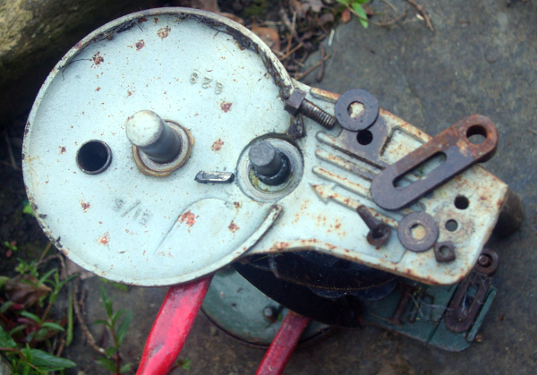
You can now undo the bolt (13) and washer (33) holding the sole plate (11).
The original one has a square head so your socket set and ring spanners will not work.
You can also undo the coach bolt (10), nut (32a) and washer (32) holding the roller carrier (7).
Again, it's a square-headed nut.
|
|
Step 5.
Now turn the mower the usual way up - having put the nuts and bolts, etc. safely away.
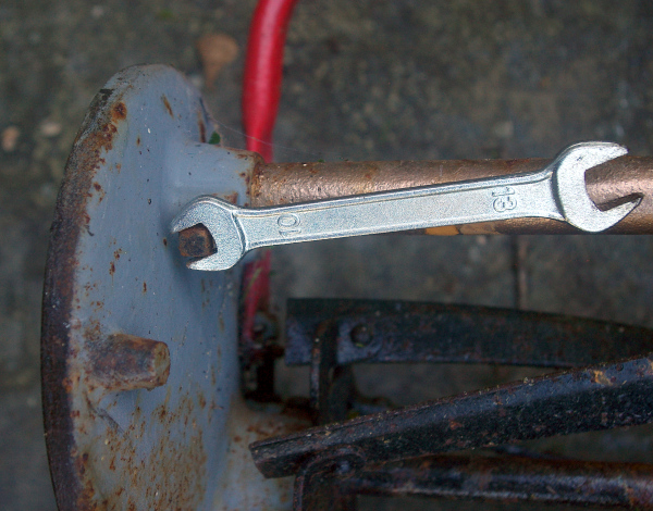
This shows one of the screws (38) which locate the front tube (35).
Again, they have a square head. I found that an 8mm spanner worked to undo one and a 10mm the other.
However, I found it convenient to only remove one side.
|
|
Step 6.
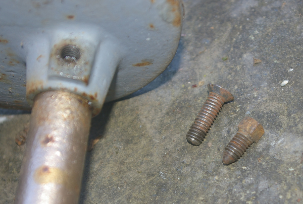
I had to replace one front tube (35) screw (38).
The photo shows the original on the right and a matching-thread one which I found and then sawed off and filed down the end.
|
|
Step 7.
Now you can remove the L.H. wheel (as above).
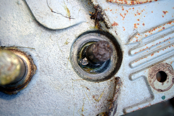
This blurred photo shows the pawl (4) on the L.H. side which is a different way round to the R.H. one.
|
|
Step 8.
Now is a good time to remove the handle (37) which has been so useful in steadying the mower while you have worked on it.
It's held in place by split pins (34) which you can remove with a pair of pliers.
|
|
Step 9.
Now remove the bronze bearing adjusting screws (27) and their lock nuts.
Next, you can split the two sides.
I found that I had to twist them a little, back and forth, whilst pulling them apart, in order to free up the front tube (35).
Once split, you will be able to access the bronze bearing bushes (28) which will undoubtedly need a good clean-up.
|
|
Step 10.
Now it is easy to access the adjusting bolts, etc.
These will all need a good soaking in penetrating oil.
The top one in the picture is the handle adjusting bolt and nut (31).
If you have to replace this one, note that using too long a bolt will result in it blocking access to adjust the lower screws.
Also note that the mower can operate quite well with only this bolt only fitted on one side.
The lower two are the sole plate adjustment screws (9) designed to be turned with a flat-head screwdriver.
|
|
Step 11.
This shows all the parts, largely de-greased (using Gunk) and ready to decorate.
I next treated the rusty parts with Hammerite Kurust.
Before painting, I stuffed some paper into each of the holes - to prevent paint fouling the threads.
|
|
Reassembly.
|
Step 12.
This shows one of the bronze bearing bushes (28) before slotting it in it's hole.
There is a lip at the other end of the hole which locates it at the correct depth.
Note the recess into which the bronze bearing adjusting screw (27) will fit.
|
|
Step 13.
This shows one of the bronze bearing bushes (28) in it's hole.
Note that the slot in the bearing should align with the greasing hole in the side plate assembly (5 or 6).
The bronze bearing adjusting screw (27) should now be tightened enough to fix the bearing in place.
It can be tightened later if the cylinder assembly (15, etc.) is loose.
Now fit the cylinder assembly and front tube (35) into the two sides.
The front tube (35) will just project on the other side of the side plate - see the picture for Step 13 above.
The screws (38) which lock the front tube in place will need to locate in the dents in the tube which they have previously made.
Do not tighten them fully yet - wait 'till the sole plate has been fitted later on.
|
|
Step 14.
You will now be ready to refit the two pinions (2 and 3) (gears) and their pawls (4).
This shows them frack to bunt, sorry! The R.H. pair is on the left and the L.H. on the right.
It also shows how they engage in one direction and release in the other.
|
|
Step 15.
This shows the R.H. pinion (2) (gear) ready to slot onto the end of the cylinder spindle (15).
Its pawl (4) is in place, slotted into the greased spindle the correct way round.
|
|
Step 16.
This shows the wheel, greased and ready to refit.
Once it's in place, I suggest leaving the split pin for now - until you've checked the gears are working correctly.
|
|
Step 17.
Stand the assembly on end - holding onto the just-fitted wheel to stop it falling off.
Now you will be able to reassemble the other wheel in the same way.
Once in place, try rotating each wheel in turn, the correct way for mowing. The cylinder assembly (15, etc.) should turn in the right direction. This will show if you've got the gears the right way round.
If not, bad luck, you will need to swap the pinions (2 and 3) (gears) and their pawls (4).
If it is OK, then you can re-insert the split pins (8) in the wheels, with a bit of grease.
Then there's the spigot cover assemblies (36) (wheel caps) to clip in place.
|
|
Step 18.
Now you can refit the sole plate (11) and bottom blade (17) using the screw (13) (bolt).
You will have spotted that I didn't split the sole plate and blade in my renovation (it didn't seem necessary) so I can't advise on any problems you may find if you need to do so.
Don't over-tighten this screw as the sole plate has to be able to rotate.
However, doing it up will pull the two sides together the correct distance.
The screws (38) which lock the front tube (35) in place can now be fully tightened.
You will now need to fiddle with the sole plate adjustment screws (9 A and B) so that the blades are just rubbing together.
|
|
Step 19.
Here is my reconditioned mower, which works quietly and well.
Since I'm not entering it in any shows, I haven't kept to the correct colours throughout - just used what paint I had lying about.
|
|
Finally.
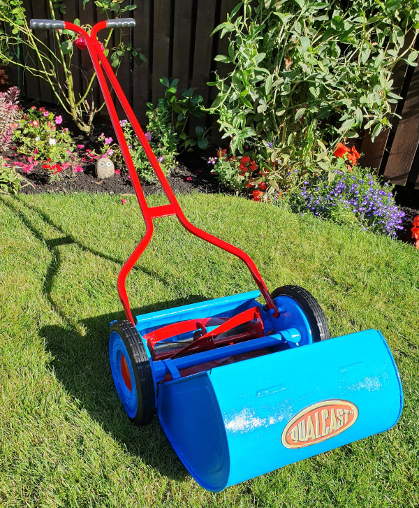
Here is a picture of Derek McLeod's Qualcast B1, after a thorough renovation.
You can see the tyres which seem to be the only difference between it and the E1.
|
|
Please let me know if the above helped, or if you found any mistakes or better solutions (see below).
This page last updated 14th. August 2020.
Images and text © Copyright Jim Batten, 2019-2020.
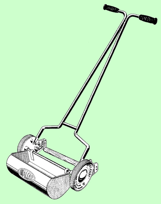 If you don't have a Qualcast E1 lawn mower, then this web page may still help with other push mower problems. The Qualcast B1 appears to be very much the same, but with rubber tyres.
 If you don't have a Qualcast E1 lawn mower, then this web page may still help with other push mower problems. The Qualcast B1 appears to be very much the same, but with rubber tyres.